Introduction
Diameter: 58mm
Length: 2251mm
Weight fully loaded: 5500gr (of which approximately 1700gr propellant)
Motor: DECA 12 grain KNER
Cd estimate: 0,67
News
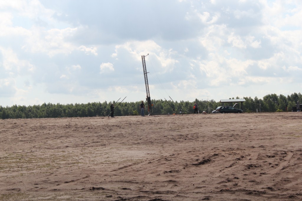
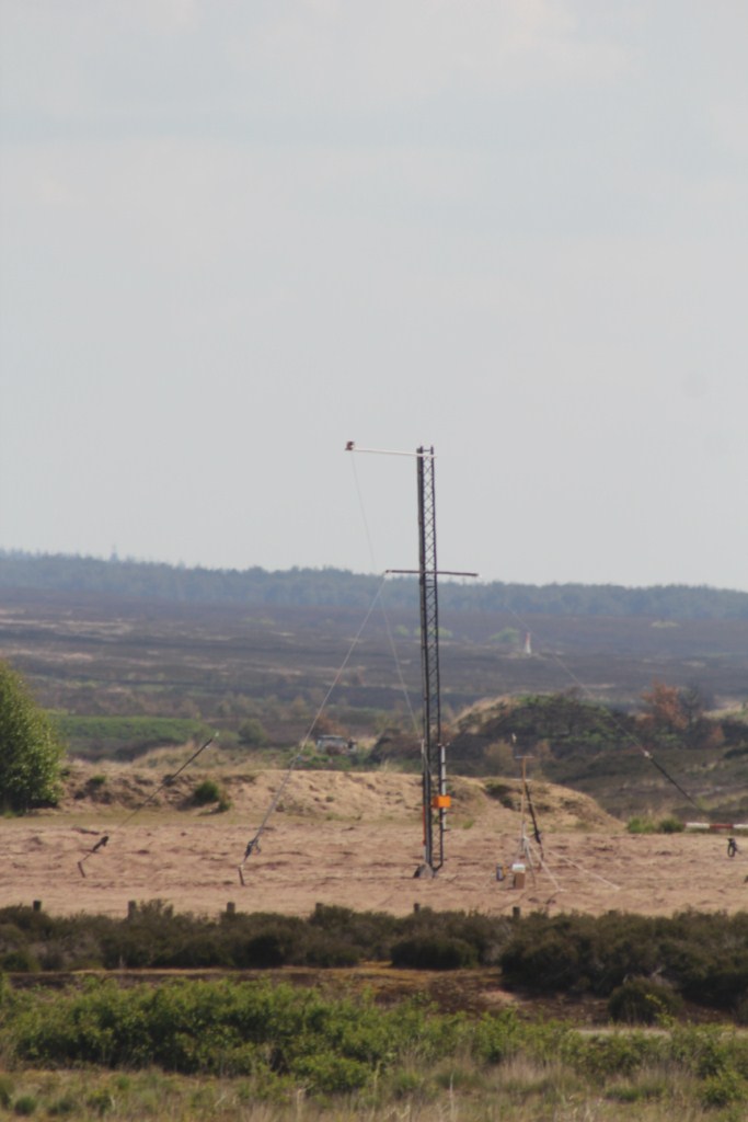
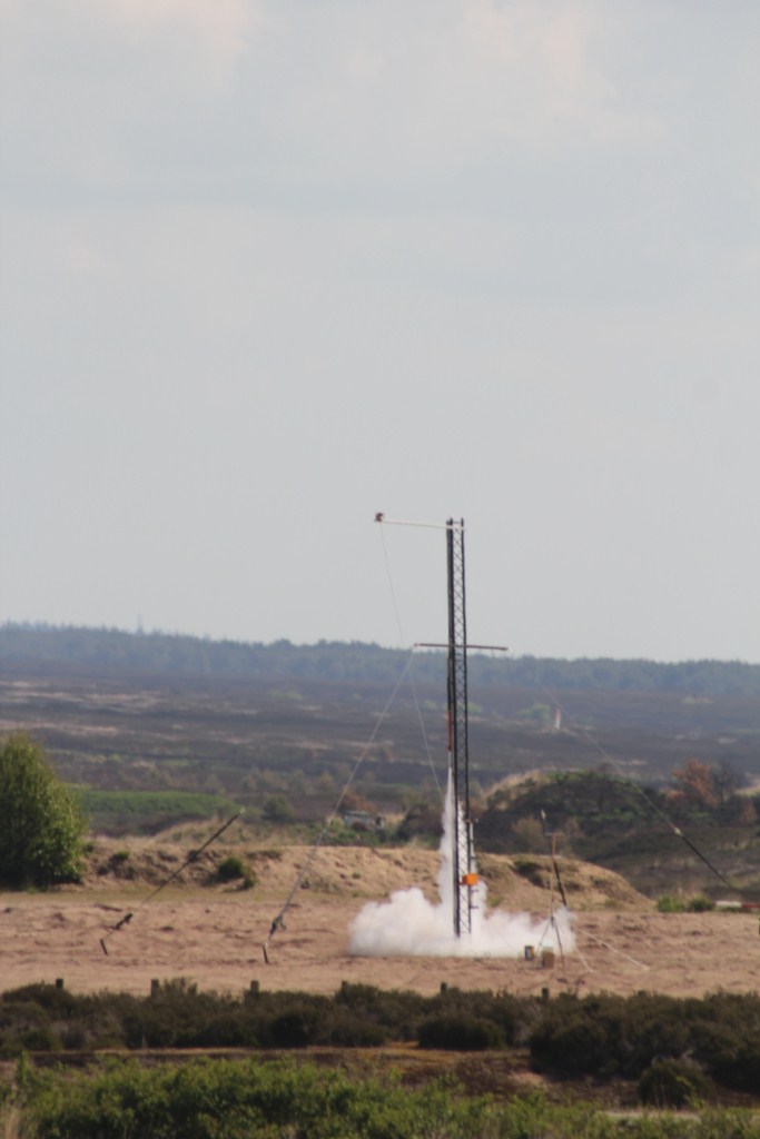
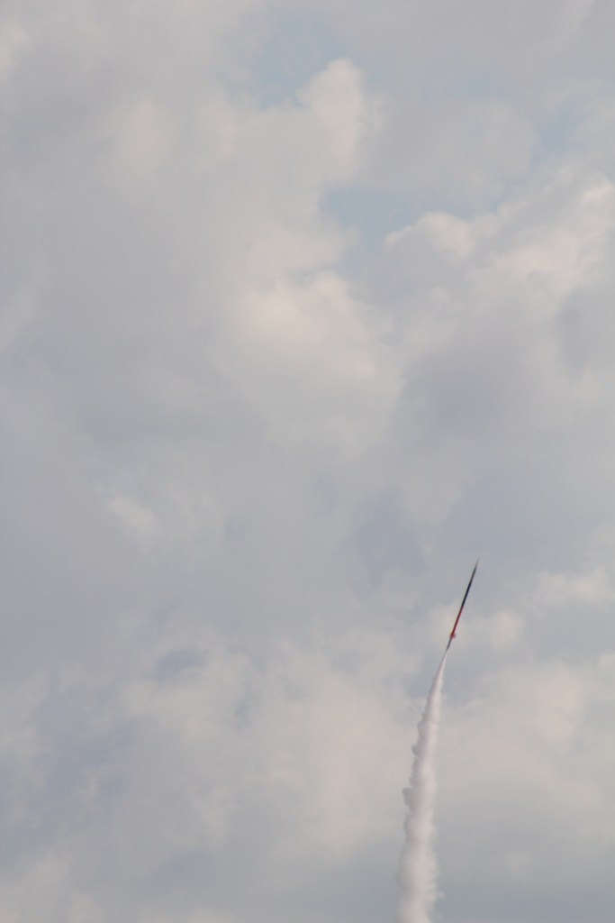
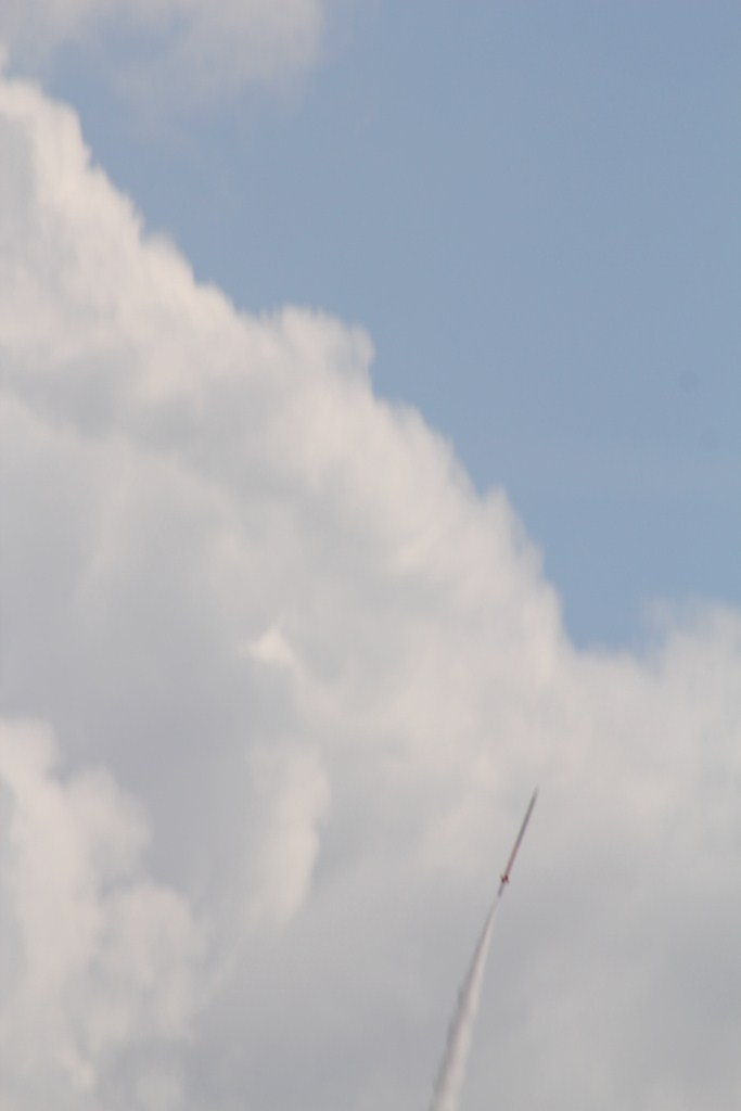
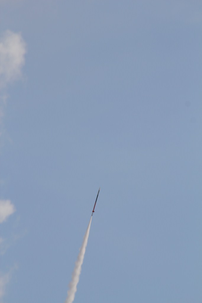
13.05.2011 – DECA was launched onboard video – DECA III – flight 13.05.2011
Extensive flight analysis presentation by BO – H14C flight analysis presentation (7)
19.04.2011- Pre-flight data – DECA-III-H14C-Flight-I-13.05.2011
Goals
- Achieve a peak altitude of 2,9 – 3 km
- Achieve a maximum velocity of 300m/s, or 1000+km/h
- Re-think the building procedure and built a new fin can to reduce spinning
- Work out a new recovery scheme with the use of a cable tie cutter
- Check usability of a GOPRO HD HERO as onboard camera – probably not available at launch date
- Test 9 x 6 mm latex tubing for the pyro charges – probably not available at launch date
Design & Construction
Motor:
Motor is the DECA 12 grain KNER. In design it is quite similar to the 54mm DECA 8 grain motor however carrying 12 bates grains for propellant. Total impuls is approximately 1730Ns with a low specific impulse (105s) due to low chamber pressure. The nozzle has a 16mm throat and is optimised for the 20mm core Bates grains (core-to-throat ratio of about 1,5:1 to avoid erosive burning). Ae/At ratio is 6,0:1. The nozzle is held in place with 2 rows of 6x – M3 countersunk hex socket bolts. Forward bulkhead is retained by the coupler which is secured the same way as the nozzle. Liner is made out if 1mm thick EPDM foil – 1,25 x ID motor wrap.
04.09.10 – Static tested – 54mm, 12 BATES grains, KNER 6535 Static Test I – 04.09.10
Fin can:
Fin can was built according this page: Composite fin can 54mm rocket & 54mm fin alignment jig
Fin can mass: 315gr. CoG @ 314mm from short end. Length cylindrical part = 744mm.
Recovery section:
Unlike the succesfull DECA II rocket, this rocket will break up only above the motor. During flight motor and airframe sections will be held together by 2pieces 8-10mm wide – aluminium tape strips. At apogee a 1,2 gram straw charge will seperate the rocket into 2 sections at the motor / airframe coupler and tear the aluminium tapes. This will provide 1st stage tumble recovery and also ejects the main parachute burrito. This kevlar burrito is tightly retained with a calbe tie which will be released by a smart cutter at 300m. This approach will reduce the break up points from two to only one, has a length reduction of 150mm (3 calibers) and provides a more rigid rocket for those upcoming high speed / high altitude launches. The airframe has changed to 54mm G12 airframe HPR body tube 57,8×54,6mm. Due to the slightly larger inner diameter the length was again shortened to a final length of 600mm.
- 5 meters of 3,2mm tubular kevlar shock cord for the first stage tumble recovery. In the middle of the shock cord a swivel is mounted to reduce spinning caused by the motor and fin section.
- Main parachute (800mm diameter) with kevlar cloth burrito style wrap & cable tie cutter
- Gps tracker
- Recovery electronics bay which is positioned at the top of the tube. Recovery electronics / payload couplers is retained by 6x M3 countersunk hex socket bolts. Only the floating bulkhead is exposed to the recovery charges and therefore has a 50x42mm O-ring to protect the recovery electronics from the hot gasses.
- Attached to the recovery electronics / payload coupler is a removable payload & nose cone made out of HPR materials.
Drawings – 54.03.00.00_DECA_Rocket – 11.11.2010
Recovery test 19.03.2011:
First of all the cable tie cutter was tested stand alone to check its function. A mere 0,3gram coarse BP charge was used in combination with a fuse head. The fuse head wire was secured to the case with hot melt glue. Two options were tested: a) hot melt glue applied from the inside and b) hot melt glue applied from the outside. Both methods proved to function excellent however hot melt glue from the inside would be the preferred method for future use. The 2,5mm x 100mm cable tie was severed confidently and sprung away from the cutter (this favourable phenomenon was also observed in the actual test). The 0,3gram charge provide to be spot on. Taping the case to the kevlar piston retaining chord worked perfectly and all objects were safely retained.
Cable tie cutter test – 19.03.2011
Secondly the airframe/motor separation charge was tested. Airframe was loaded with the recovery system as it would have been an actual flight. A 1,2gram apogee straw charge was used. This straw charge was protected from buckling during preparations by a 1m section of small diameter pipe. Subsequently the recovery system was inserted into the airframe and the pipe extracted. The sections were taped together with 2 pieces of 10-11 mm wide aluminium tape (worst-case scenario) which would shear to separate the airframe from the motor. The apogee charge separated both sections about 1 meter from each other and ejected the parachute burrito out of the airframe. For the forthcoming flight, 2 piece of 8mm wide aluminium tape will be used to make sure the sections will separate. Test was found to satisfactory separate the 2 sections and to eject the parachute burrito. A larger charge could be used to have a more confident separation but is not deemed necessary. The clay filled cable passage was found to be doubtful (due to movement of the cables) and will be replaced before the flight with the proven cable gland filled with clay.
Thirdly the cable tie cutter was tested as it was ejected with the parachute burrito during the previous test similar to a flight. The twisted wire functioned OK and maintained structural integrity during parachute ejection even though a small section was briefly exposed to the hot BP gasses. The cable tie cutter severed cable tie with a small but controlled “pop”. Again the severed cable tie sprung away from the cutter thereby clearing the parachute burrito which easily fell out of its kevlar protection. The result would be a perfect recovery and other than the cable gland no modifications are needed for the forth coming flight.
Click here for a video clip of the static recovery test: 54mm, DECA III rocket, static recovery test – 19.03.2011
Recovery notes:
- Main parachute 800mm diameter + 1m tubular kevlar with end pliced for connection to d-shackle.
- Burrito style parachute flame protection. Kevlar cloth 460 x 235mm. Length = spare (60mm) + length parachute (260mm) +GPS tracker (70mm) + overlap (70mm) = 460mm. Width = 1,5 · π · ID tube = 235mm.
- *** OPTIONAL *** Have to test a new type of container for the pyro charges. A 2 1/2″ long piece of latex tubing also known as “surgical tubing”, (tubing is 7/16″ – 10.94mm OD and 1/4″ – 6.25mm ID. Test size: 9x6mm. High Altitude Deployment
- DECA III descent actuals – Flight I 13-05-2011
- Tumble free fall DECA III rocket = 25.3m/s. Under parachute = 12.5m/s. Weight rocket 3,8kg.
- DECA II descent actuals – Flight I 07-05-2010
- Tumble free fall DECA II rocket = 30m/s. Under parachute = 14m/s. Weight rocket 4,8kg.
Payload
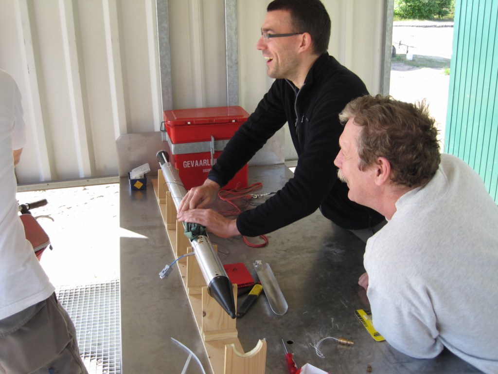
Payload built by BO and will contain:
- RDAS Tiny
- IMU
- I-AM sensor package
- Video camera
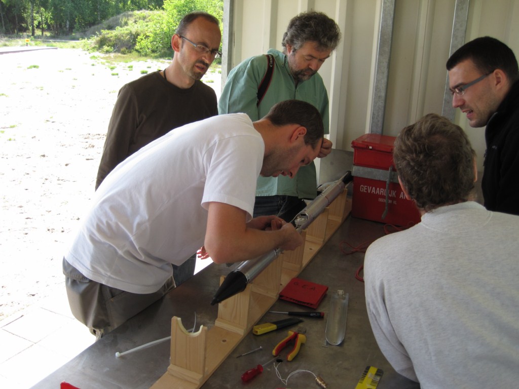
04.09.10 – Assembled rocket & payload. Determined Cp & Cg. Static margin of 1,52 cal.
Notes
Length:
- Parachute in GF tube: 200mm
- First stage kevlar shock cord: 100mm
- GPS tracker: 65mm
Glass Body tube
- OD = 57.8mm
- ID = 54.6mm
Glass Coupler tube
- OD 54.5mm
- ID = 50.9mm
Machining the glass tube to length: While cutting the tube square on a lathe don’t go all the way and leave 0,4mm wall thichness remaining. Final cut by hand with sharp hobby knife. This to prevent glass fiber weave to catch up with cutting tool thereby causing delamination of inner layer of glassfiber.
Conclusions
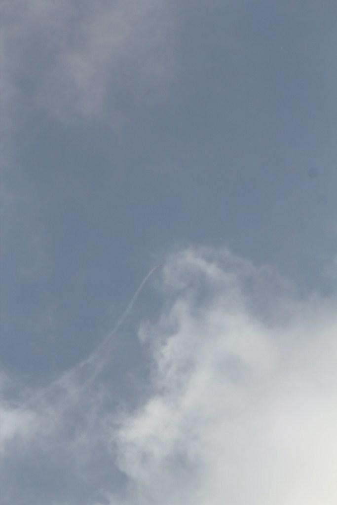
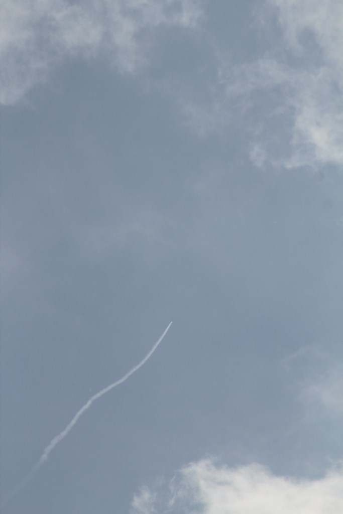
- Achieve a peak altitude of 2,9 – 3 km – Peak altitude was missed by 700m due to a sudden course change at 6,5s into the flight while heavily cork srewing
- Achieve a maximum velocity of 300m/s – Maximum velocity was 280m/s and did not match with the simulated 300m/s due to a under performing motor.
- Re-think the building procedure and built a new fin can to reduce spinning – Fin can turned out to have no measurable difference in fin alignment but has a 2Hz spin @ 280m/s. Although the onboard movie is useless, 2Hz at 280m/s is considered reasonable. A longer fin, fin root 3 calibers long instead of 2 calibers, could make fin alignment even better and reduce spinning. Small discrepansies between the difference of sanding the leading edges could also casue a spinning motion.
- Work out a new recovery scheme with the use of a cable tie cutter – BP charge at apogee to seperate the rocket and the cable tie cutter to release the parachute burrito proved to work reliably for a 2 stage receovery. A tangling of the shock cord and the fin can was observed during analysis of the onboard movie. A healthier ejection charge could be used to have a more forcefull separation between the 2 parts which would fully extend the shock cord.
- Check usability of a GOPRO HD HERO as onboard camera – Not available at launch date
- Test 9 x 6 mm latex tubing for the pyro charges – Decided to keep the proven straw igniter and protect it during assembly with a brass pipe section which was removed shortly before coupling of the receovery section to the motor.
Post flight analysis – by BO
- Interesting post flight analysis DECA III by BO – H14C flight analysis presentation (7) This report was much appreciated during the determination of “what went wrong” and includes an analysis of the RDAS, IR sensors & onboard camera.
Library
- NERO Basic RSDS & Aerolab file – DECA-III-H14C-Flight-I-13.05.2011
- Manual of GoPro Hero HD – HD_HERO
- RDAS Tiny – RDAS Tiny addendum – 15.04.10
- Manual Mini Real-Time Spy GSM GPRS GPS Tracker, Tracking Device – Manual GPS tracker
- Turnigy camera manual – Turnigy highrate 30FPS Ultra-small Digital Camera W/ 2GB SanDisk Micro SD

